
Positioning an environmental sensor correctly is one of the best methods to obtain high-quality measurements. Incorrectly positioning an environmental sensor could render data useless. Hence it is important to consider as many factors as possible to ensure correct sensor positioning.
We focus specifically on positioning solar irradiance sensors. These include our pyranometers, pyrheliometers and pyrgeometers.

Obstacles
One of the most important factors when positioning an environmental sensor is obstacles. Despite its importance and obviousness, obstacles affecting measurements are often overlooked with a cursory ‘she’ll be right’.
What constitutes an obstacle? This is difficult to answer and will vary with each instrument and manufacturer. However, broadly speaking an obstacle is something which that will interfere with the inputs to the sensor. This could be through reflections or shading.
Obstacles and solar irradiance sensors
Solar irradiance sensors measure the sun’s radiation throughout the day. If an obstacle casts a shadow over the sensor it will reduce irradiance received. Some obstacles are obvious, such as nearby trees and buildings. However, when assessing such obstacles it is important to consider the length of shadow they will cast at sunset and sunrise (when their shadows are longest). During these times irradiance is at its minimum, so even the smallest amount of shading will compromise results.
Obstacles don’t just cause shadows. In some cases, they can reflect light onto an irradiance sensor causing greater inputs to be higher than the actual levels. The level of reflected radiation will depend on various factors, such as size, distance, materials, and the coating. Light coloured objects will reflect more than darker objects.
Positioning an environmental sensor – how to minimise or avoid shading.
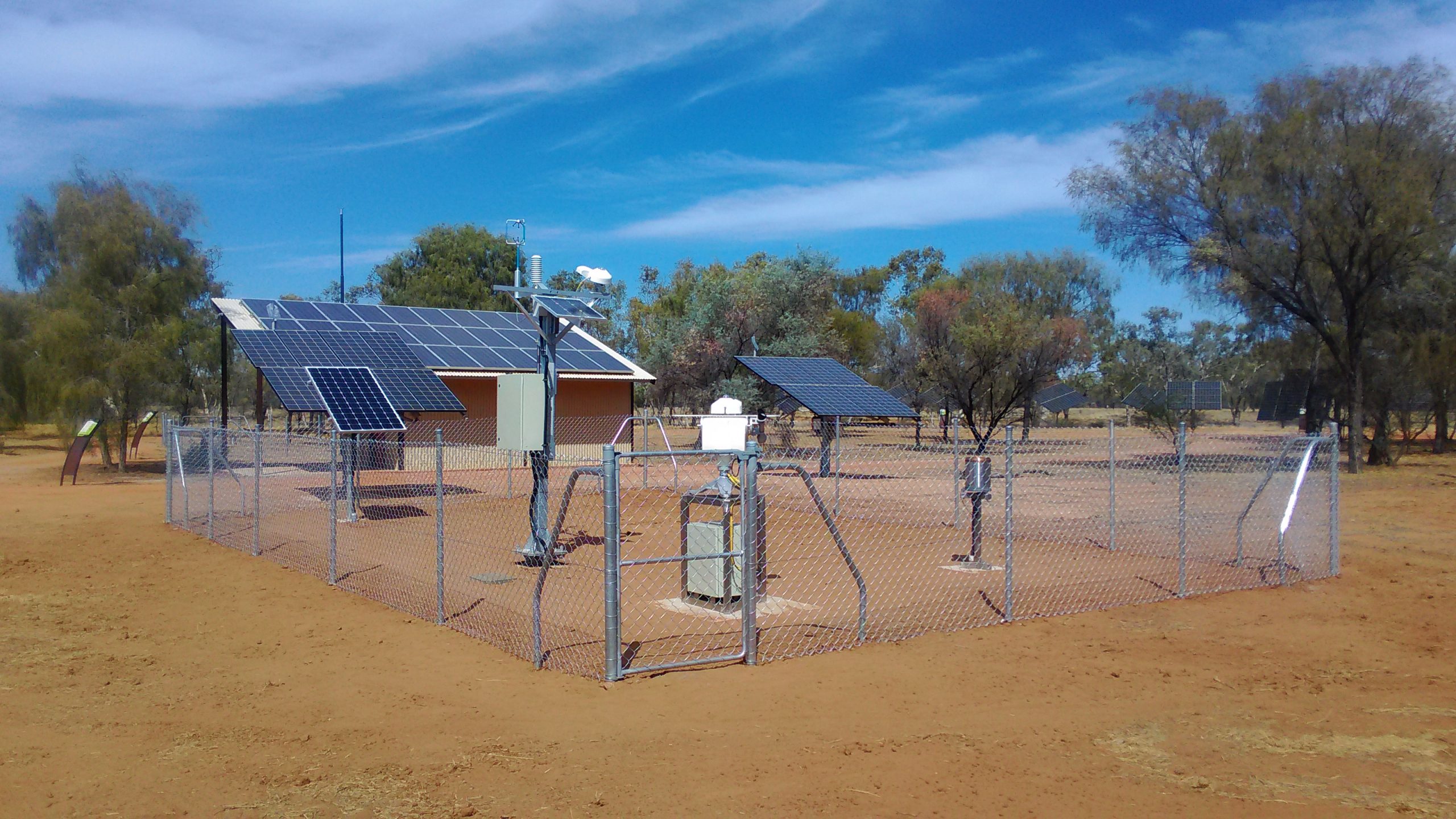
As a general rule, irradiance sensors should be positioned 10 x the height of the nearest obstacle away. For instance, if a nearby tree is 10m high, the sensor should be positioned 100m away. Depending on the situation this sometimes requires site planning. Having such space available isn’t always possible without clearing an area first. Something which could have considerable environmental impacts. In situations where using the 10 x rule isn’t possible, consider where the sensor positioning is, in relation to obstructions. For example, positioning a sensor to avoid shadows specifically during sunset and/or sunrise could be a good compromise. In the photograph above (showing SOLYS2 and Pyranometer) the sensors are positioned within a specifically made clearing prevented sensor shadowing.

For albedometers, painting the mounting pole black will reduce the reflection of radiation onto the downward-facing pyranometer. Limiting mounting pole diameter also reduces reflection by reducing potential reflective surface area. As a final precaution, raise an albedometer by 2-3 meters (The WMO recommends a height of 1 m to 2 m above a uniform surface covered by short grass). As such, consideration of nearby ground obstacles and roughness is necessary to avoid measurement interference. The same applies to albedometer mounting structures and poles.
For weather stations, considering the relative location sensors to one another is necessary. It is possible with some setups to accidentally shadow other sensors. For example, a pyranometer could disrupt the flow of the wind over anemometers and wind vanes if positioned in their paths. Using separate masts and distancing them can negate this, along with considering sensor positions on the mast.
Alignment
Alignment is a key factor for high-quality measurements. For pyranometers, pyrgeometers, and net radiometers, the level bubble helps make very small adjustments in the right direction. Pyranometer’s and pyrgeometer’s legs individually adjust, which further helps accommodate very small changes. The small changes will ensure the 180° field of view is being optimised. Of course, pyranometers angled to match solar installation’s plane of array should be angled accordingly. Even so, consideration should be taken to ensure the plane of array is matched.
For pyrheliometers alignment is fundamental. Pyrheliometers have a narrow field of view (approximately 5 degrees), as a result, only direct normal irradiance (DNI) reaches the sensor. For optimal measurements, pyrheliometers must point directly towards the sun at all times. When attached to a sun tracker, a pyrheliometer will be aimed exactly at the sun. However, it is important to use a high-quality sun tracker (such as a SOLYS2) to ensure year-round alignment. Trackers with GPS tracking and gear drives will further improve accuracy. Though, even with trackers such as the SOLY2 adjustments may be required throughout the year to ensure the pyrheliometer is actually positioned and mounted correctly on the tracker.

Kipp and Zonen manuals which feature positioning advice can be found here.